Introduction
Several examples of mechatronic systems can be found nowadays in modern cars, production systems, and medical technology. Day by day, the number of innovative functionalities in such mechatronic systems is increasing. These functionalities are realized with complex software. Such software exhibits hard real-time, safety requirements. The adherence to these requirements must be thoroughly analyzed and verified. Moreover, to obtain a significant increment in the reliability, performance, and efficiency of such software, it needs to maintain the self-adaptation of its properties.
In order to develop such systems with a high quality and within a short time, we need a systematic and consistent design method. For this purpose, the software engineering group at the University of Paderborn and the Fraunhofer IEM in Paderborn propose the MechatronicUML method. This method provides a comprehensive model-driven process support, that starts from requirements and reaches the executable software after passing through several design and analysis steps. This process improves the comprehension during development and makes complex systems manageable. MechatronicUML emphasizes mainly on:
- modeling and (formal) verification of reconfigurable software architectures,
- the coordination among system components in such architectures,
- the integration of discrete software events with the continuous behavior of control devices, and
- the hazard analysis for detecting probable influences of random hardware failures.


The MechatronicUML Development Method
MechatronicUML defines a systematic, iterative development method. The user can derive the implementation of software from the formal specification of required software subsystems (Components). Afterwards, you may define the asynchronous communication between components by using the Communication Protocols. The behavior of the software components is built by Real-Time Statecharts (an extension to UML state machines) which are integrated into the whole system architecture. Figure 1 gives an overview of the development process.
The MechatronicUML Language
MechatronicUML offers you a suitable language for designing your software architecture. You design your architecture with means of hierarchical software components that communicate through ports. MechatronicUML supports also the modeling of continuous ports to integrate the controller behavior. You describe the real-time constraints and the discrete system behavior by using the Real-Time Statecharts that are assigned to different ports. These Real-Time Statecharts define reusable Coordination Protocols which supports the verification of the whole system. We illustrate the MechatronicUML modeling language with a simple example in Figure 2.
Analysis with MechatronicUML
MechatronicUML offers a set of integrated analyses steps, with which you can verify your models. Thereby, you use existing verification techniques and tools for proving the correctness of discrete behavior, while considering real-time constraints according to the system specification. For an early analysis of your mechatronic systems (starting at the beginning of the software development phases), we offer the ability to formally verify your MechatronicUML models – all execution paths would be examined with our analysis. For this purpose, we use the model checker UPPAAL. Besides the formal verification, it is possible to simulate your models using MATLAB® Simulink®, Modelica®, or the Functional Mock-up Interface (FMI). This simulation enables the validation of your system with respect to its discrete software models, its control components, and especially its physics.
Software Reconfiguration
Software Reconfiguration enables you to design your system so that it adapts automatically at runtime according to the changing environment conditions. This significantly increases the reliability, performance, and the efficiency of your system. The reconfigurability targets especially the design of discrete, state-based system behavior. With MechatronicUML, you can integrate and coordinate different control strategies in order to implement the system continuous behavior.
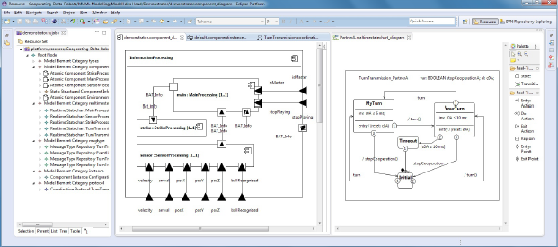
Tool Support
The MechatronicUML Tool-Suite (formerly known as Fujaba Real-Time Tool-Suite) is our award-winning research-prototype, in which we apply our latest research knowledge in the field of MechatronicUML. Figure 3 shows a screenshot of our tool suite. It is available in the download section. The embedded modeler from our partner Solunar GmbH is a another good starting point for the software design with MechatronicUML.
*
IBM Eclipse Innovation Award 2004
IBM Eclipse Real-time Innovation Award 2008
Documentation

MechatronicUML Requirements Specification
Our specification provides detailed insight about the process and the language for the requirements engineering method using MechatronicUML.